How I built a very heavy jet engine from a turbocharger....2012
I know, you are thinking 'not another turbo-charger gas turbine site', well, yes it is but somewhat different from the others in that I built a combustion chamber that is in line, not with the air inlet as a side entry. The turbo is a Garret from a Linde fork truck, originally on a Volkswagen engine. I work at a factory that has great metalworking facilities, such as a full fab shop, machine shop and also that time saving instrument, a programmable plasma cutter (it will cut any shape from sheet steel you could imagine).
I started this project a few years ago and got held up due to the birth of my twin boys Charlie and Niall, now they are 3 I feel it is ok to carry on with the project and get them involved, though for the risky and slightly dangerous starting up for the first time part they will be well out of harms way.
I have an interest in Steampunk also and can relate some of the gas turbine and oil pump design and look to this great idea that is Victorian ingenuity mixed up with Science Fiction (sort of), so not painting the machine kind of adds to the Steampunk overall look, although as in the above photo of the almost completed gas turbine the blue silicon hose looks too modern and will probably be replaced with some black hose salvaged from somewhere.
Enough waffle for now, here are some more pictures.
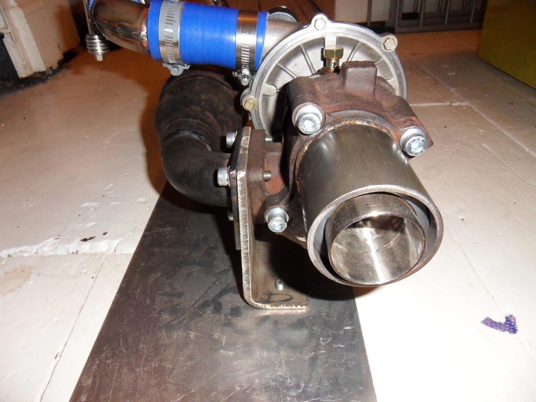
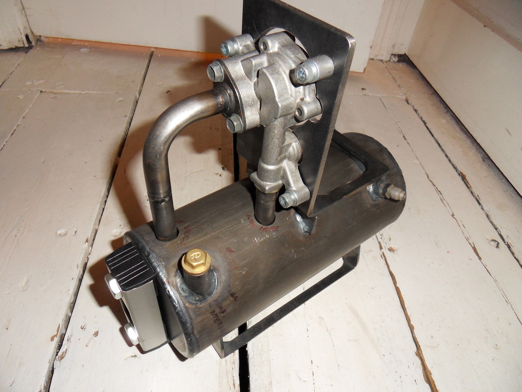
Main pic of nearly completed Gas Turbine with the Oil Pump & attached tank
Principle of Operation
Basically the fuel will be propane gas fed from an adjustable regulator. The ignition will be from a glow plug and exhaust temperature, boost pressure, oil level and temperature will be monitored. Starting will probably be compressed air spooling up the compressor. The oil pump and glow plug will be run off a 12V battery as will probably the starter system.
Exhaust End
A view of the exhaust end, the temperature should be around 500 degrees C (sorry folks, no degrees F here, this is an English site !)
There is still a waste gate fitted to the lower part of the exhaust turbine chamber, this has a lever to actuate and needs to be pulled closed somehow, I will probably fit a heavy spring on it. Note the inner exhaust tube is stainless steel, the rest is mild steel welded to the casting of the turbo (some nice TIG welding by a mate, a much neater finish that MIG).
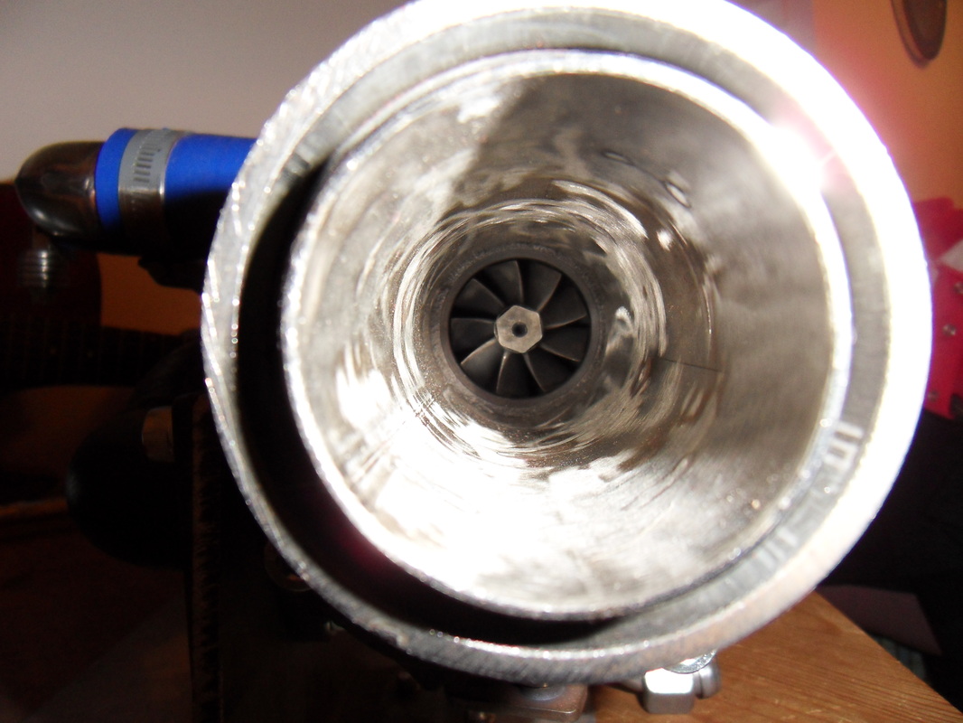
Up the business end
A close up of the exhaust turbine wheel. This is made of a high nickel superalloy that can withstand very high heat temperatures. During the running of the jet engine temperatures exiting the turbine wheel exhaust will be in the region of 500℃.
SAFETY WARNING !! Some turbine wheels suffer from tip melting if for example the burner heat is too high, resulting in very hot high speed pieces of metal being ejected from the exhaust gas stream.
DO NOT LOOK DIRECTLY AT THE EXHAUST TURBINE unless adequate safety precautions are taken.
Note that probably the best place to stand when the engine is running in my opinion is looking at the air inlet compressor end. Note that turbine rotors can shatter so there is a risk that a shattered wheel could punch its way out of a turbo casing (although modern turbo's are strong in normal operation, making a turbo into a jet engine is not normal operation and can result in much higher rotational speeds that the turbo is originally designed to reach !!).
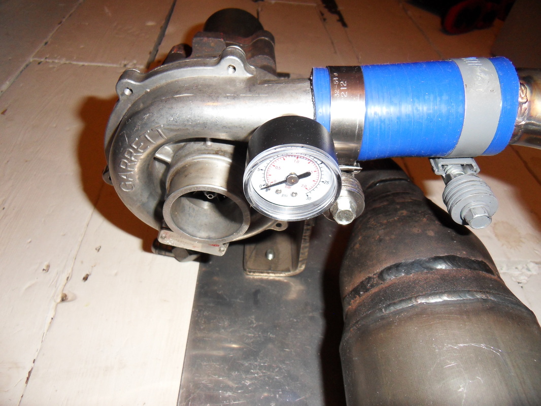
Air Inlet End (Compressor Turbine)
The turbocharger utilises a centrifugal compressor wheel as used on the early jet engines made by Frank Whittle and Hans Joachim Pabst von Ohain, although both designs used a double sided compressor wheel.
I have fitted a gauge (2 bar) to an empty port in the scroll face, not sure if it will register some boost pressure but the gauge was £2.50 from e-bay and it looked ok so it stays unless it does not register any pressure.
There is another small port that I may fit a small section of copper or brass pipe to, bash the end almost flat to form a fan shaped air jet and spray cool air between the blue silicon hose and the combustion chamber to the right of the picture, this should stop the silicone hose from catching fire due to the at from the combustion chamber, I have seen some video clips of the chambers getting red hot !!
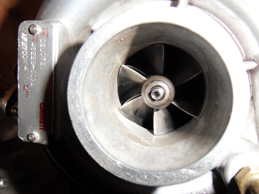
The compressor wheel inlet
A close up view of the compressor turbine. As mentioned this is a radial compressor wheel made of aluminium. There is some heat generated in the air compression process but not enough to distort or heat damage the thin vanes that make up the wheel. The spindle in the middle leads to the turbine rotor on its opposite end, the bearing is a metal to metal type so good lubrication with sufficient oil pressure is essential to the long life of the bearing / engine.
Through Flow Combustion Chamber
My own design through flow combustion chamber, the most time consuming part of the project, there are 4x gas nozzles inside, experimentation is the key with the amount of gas in the chamber, I fitted too many gas nozzles so will need to remove a couple or more to get the combustion correct. There is a lot of work in getting the air mixture correct (lots of hole drilling in the inner burner tube) but it should work ok. Hole calculations gleaned from other web sites were a major help in this design.
I know, some people seem to use a baked bean can and some tin and it works first time, this is surely true but most of the fun in the project is to engineer something that satisfies my skills as an engineer, machinist and designer. Something knocked up would be too inelegant and not look the part which for me is not what this is about. I want to build a decent piece of kit that is robust and technical looking. It also has to have that Steampunk look as much as possible, so that negates the use of baked bean tins !!
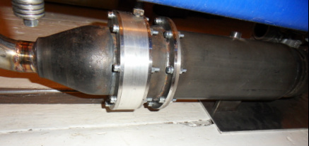
Turbine and Compressor Housing
Top view of the Gas Turbine with the exhaust turbine housing on the left and the compressor wheel housing on the right. The bolt on top is for the oil inlet supply to the metal to metal turbo shaft bearing, this is a very important part of the engine. Incorrect oil or too low oil pressure could result in bearing failure and that would mean 'Goodbye Vienna' for the turbo!.
I got quite nervous about oil pressure so decided to make an oil pump system myself.
Hidden from view is the oil drain which is directly under the oil inlet .
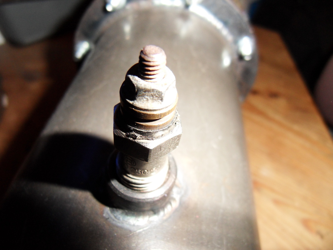
The glowplug
A glow plug is mounted on the outside of the combustion chamber, this is used to ignite the fuel. Just put 12V + on the top nut and the on the metal of the chamber and away you go, a nice bright red glow to get that burner roaring. Note the current draw is a few amps so a car battery would be a good 12v supply plus it is quite mobile if you need to run the Gas Turbine outside where a mains supply is unavailable. I also need the car battery to run the oil pump electric motor and probably to run a starter motor to get the engine spooled up so it can self sustain-though I have not built a starter motor yet.
A lot of people seem to use a leaf blower which is fine if you have one-I don't and am not keen on the idea-a fast spinning 12V electric motor seems ideal.
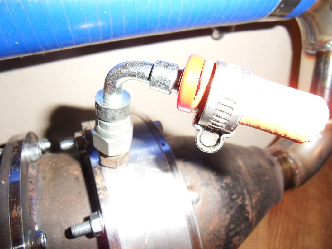
Fuel inlet
At the top of the combustion chamber is the fuel inlet fitting. I have designed the engine to work off propane gas as this is readily available and is quite easy to ignite. I would love to use jet fuel (paraffin) but the atomisation of the liquid fuel is a project for later years and not for this version of engine, although I would love to get the jet fuel smell when it spools up.
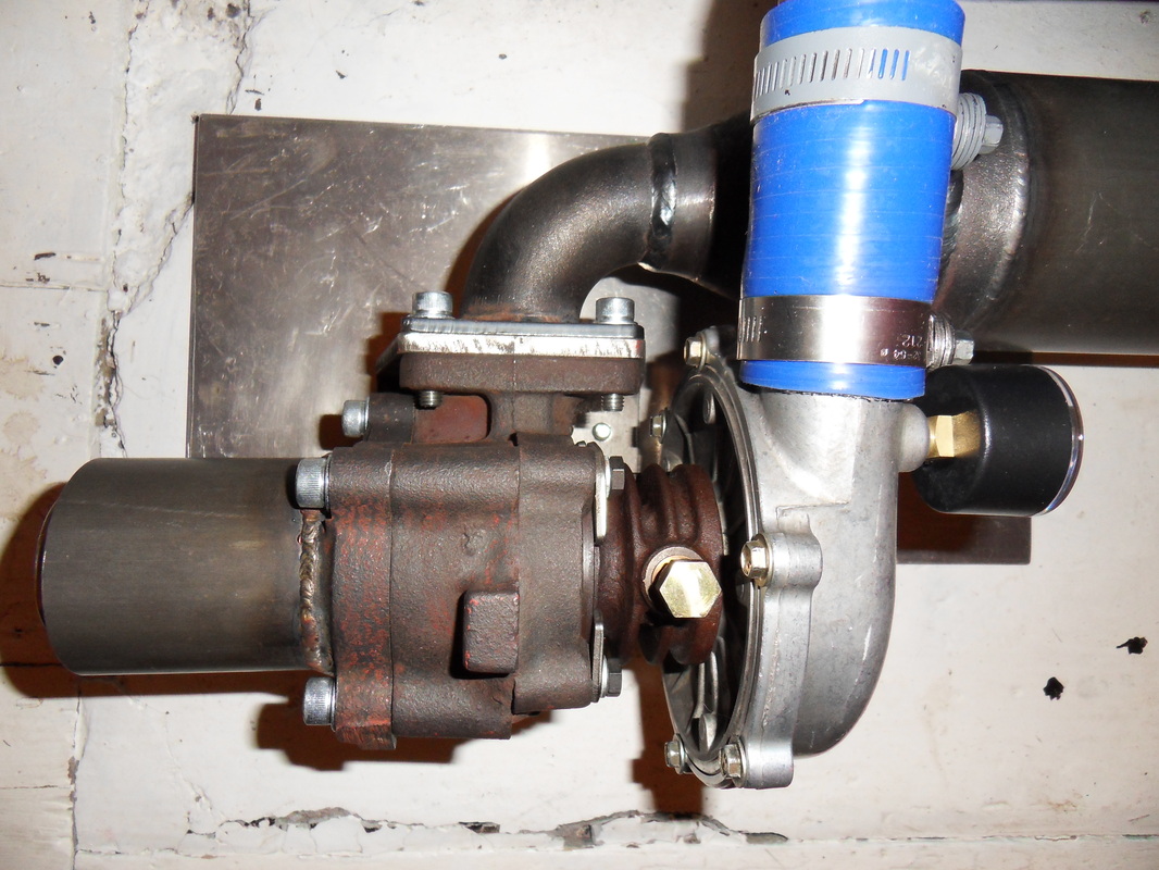
Oil Pump with Integral Oil Tank
The oil pump, bought again on e-bay. It is a motorbike gear oil pump from some 500CC Japanese bike, an old classic model CX500. It has a pressure dump return to tank which is handy if the oil pressure to the turbo bearing gets too high, then the sprung pressure relief valve will vent unused oil back to the tank.
Note on the front of the tank is a sight glass that shows me how full the tank is, it also incorporates an internal thermometer so I can see when the oil is getting too hot, hot oil seems to be a problem with home made gas turbines like these so this could be really useful.
On the left is the filling tube, the tube on the right is return to tank from the bottom drain on the turbo bearing. Note the motor needs to be properly fitted, it has no flexible coupling yet and the oil out port need s to be fixed to the pump still. Other web sites vary with the recommended oil to use, I may opt for 2 stroke oil as any oil seepage from the bearings to the exhaust turbine chamber will get burnt up quite well.
I plan to fit an oil pressure gauge (again from e-bay, £2.50) somewhere on the oil pressure output and to connect the oil pressure and return ports with that stainless steel braided hose, this looks expensive so I may not bother with this.
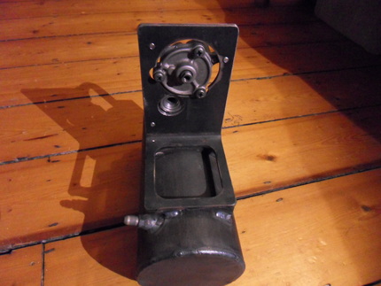
Oil pump drive end
The oil pump drive end shown will need an adaptor made to drive the (quite frankly) tiny flats on the drive shaft. The port to the left hand side is the pressure outlet.
Not my best mounting plate but 'twill suffice.
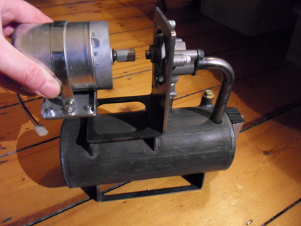
Pump drive motor
A 12V Lucas motor, off a small milling machine apparently (used to move the bed). It can rotate both directions so quite a usefull function as I am unsure what way the shaft should rotate to get oil flow!
Needs a raised mounting bracket made and a flexible coupling to allow for any axial misalignment.
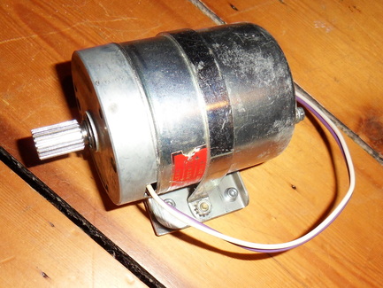
Pump motor close up
The motor does not spin that fast but has a lot of torque. It was an old servo motor from a milling machine. 12V so a good voltage for a car battery to power. It's reversible too not that I will need it to reverse. I hope the speed is enough to drive the oil pump as I have no idea what speed the pump needs to spin at in order to supply sufficiant oil flow!!
I guess I will change the motor if the flow is too slow, probably worth testing the pump with an electric drill first to see what sort of flow i get and at what optimal rpm.
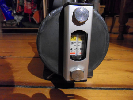
Oil tank level glass
A level glass with built in thermometer. £5 from flea-bay. I thought it would be good to know the oil level especially.
I believe the oil gets very hot to will need to keep an eye on the temperature. I may just rig up a thermocouple to monitor it more easily.
K Type digital thermocouple
This one is £4 from China, -30°C to +800°C works off 12V, seems a bargain. It may not be so accurate it may be really accurate but for montoring the oil temperature or exhaust gas temperature it seems ideal.
Can be purchased in different coloured displays if you like variety.