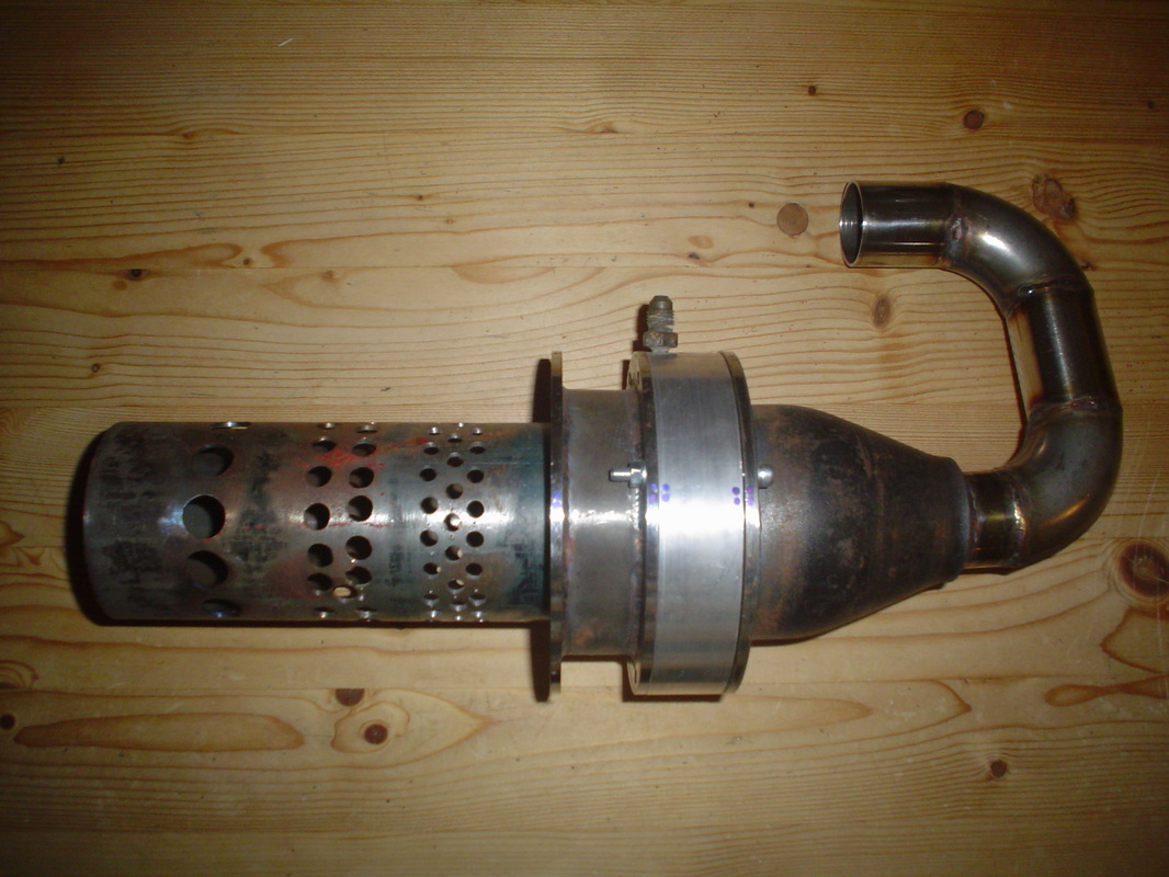
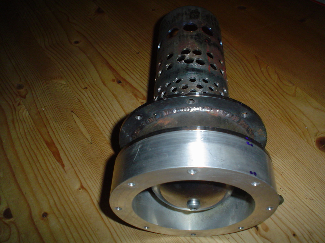
The main tube is mild steel with a series of air holes running from the gas jet end to the exit, progresivvely getting bigger. The idea is to get enough air in to the gas jet end without blowing out the flame, not as easy as it may seems. Note the fitting at the top of the alluminium section, this is the inlet for the propane. I tested this a few times with a dummy section of outer pipe to check the flame is sufficient for the job, it was (perhaps too much flame though, I will need to renmove some gas jets and run the trials again to get the correct ammount of flame).
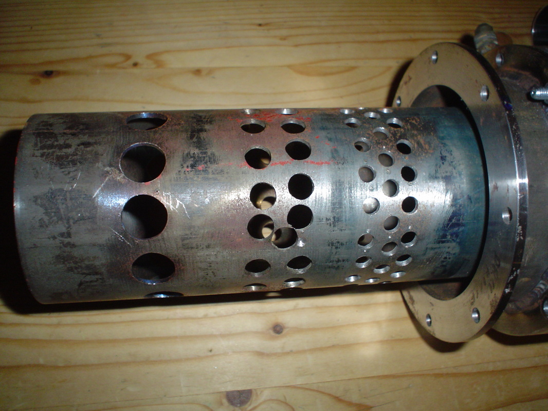
A close up of the combustion chamber air holes
The seemingly random hole in the middle section was drilled to let the glow plug (from my trusty 1.8 Peugeot 205) acess to the inside of the burner tube, looks a bit of a bodge but needs must. The holes were blimmin tricky to mark out on the pcd but I managed with a height gauge and some engineers blue.
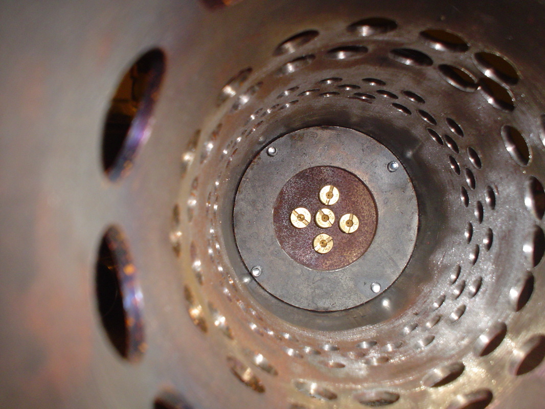
Inside view of the gas jets
These jets were off a Lambretta carb, £5 from e-bay for the lot, bargain. As mentioned too many jets so some more trials to perfect the flame. Problem is the flame roars out the end of the tube so will blow out more easily when the engine is running. Zi plan to remove a couple of the jets or three to hopefully cure the big flames.
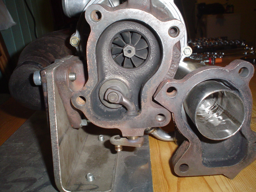
The turbine wheel & wastegate valve
The wastegate valve is no use to me for this engine so I will retain the mechanism and lock it shut. It's too much work to weld it shut and it may distort the casting.
Flame tube with domed burner cover
Just visible on the right is the gas inlet pipe, it crosses one of the quad struts. The burner tube was one of the most time consuming parts to make as calculations had to be made and holes drilled with varying hole diameters to get the correct air in to the right areas of the flame tube length. drilling was tricky but not as tricky as the hole marking out which took ages but was worth the maths and patience. The domed air diffuser was made from a stainless steel ladle from the pound shop.
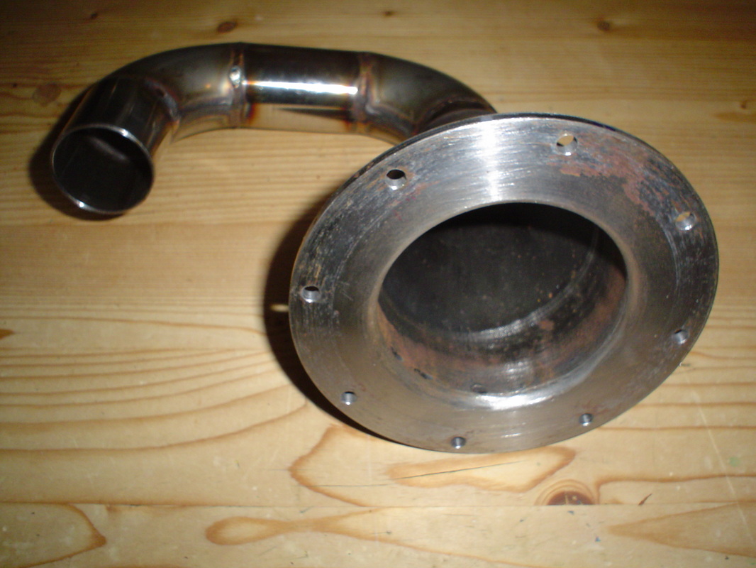
Inlet adaptor air compressor to combustion chamber
As the title says just an adaptor to get the air from the compressor outlet to the entry of the combustion chamber. the pipe sections are from stainless steel pipe and elbows used to make water pipes on diesel engines. My friend TIGGED the pipes, neat welding (much better than I cab do0.
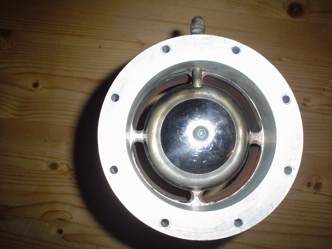
Combustion chamber air inlet end-domed air diffuser
Air exits the compressor section and hits the domed air diffuser, at the same time blowing air over one of the quad struts. One strut has the gas supply pipe running over the top of it.
The idea is to keep the gas pipe as cool as possible. I'm not too worried about the pipe connections failing due to excessive heat as they were silver soldered so should be good up to 600°C before melting, I do not believe this area of the combustion chamber will get that hot as long as the compressed air is flowing).
The stainless domed diffuser was from a Pound shop and is a ladel with the handle cut off.
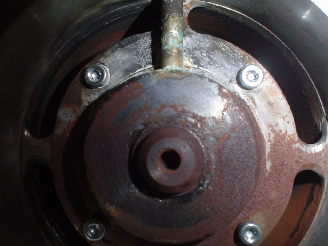
Under the domed air diffuser
View under the domed air fiffuser. The threaded hole in the centre is a blind hole to take the securing bolt.
The 4x bolts secure the burner tube back plate. Seems that after a couple of test propane burns the metal oxidises fairly quickly which is annoying.
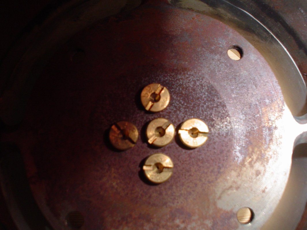
The jets (Lambretta carb jets)
I picked these up again from e bay, think about £5 for five. Testing the burner produced too long a gas flame so I will need to experiment with reducing the ammount of jest to get the best flame lengths.
The first test run: not yet
I have not finished the build yet, other projects came up (twin boys do tend to focus the mind on things not so urgent).
i do plan on conducting more work on the engine in 2021 and will update the web site then.